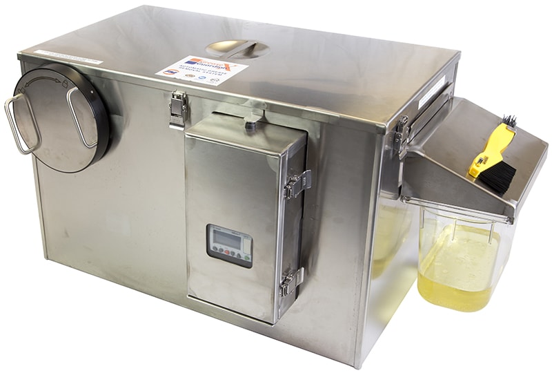
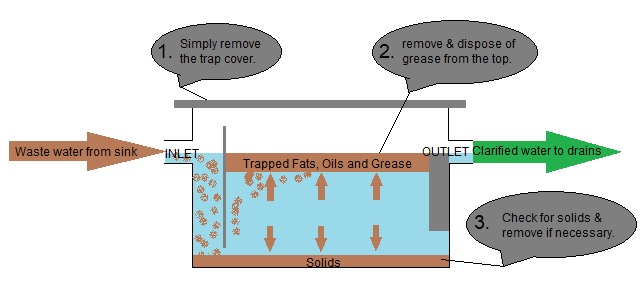
8+ grease trap diagram
CAD Drawings for Grease Traps. There are grease trap gaskets right under the cover so proceed.

Versatile Coordination Chemistry Towards Multifunctional Carbon Nanotube Nanohybrids Guldi 2006 Chemistry A European Journal Wiley Online Library
The unit before proper separation can be achieved Diagram C.

. If you think all video information are worth for you just have to pay for coffee to support channel httpswwwpaypalmeafreenaliGrease Trap Fat Trap ins. In general grease traps range from a minimum capacity of 28 m3. 7 GPM CAD Drawings Zip file.
Grease interceptors are to be installed at a distance of 8-10. 25 GPM Grease Trap CAD Drawings Zip. The oil and grease will be.
Built from 11 gauge carbon steel with a corrosion resistant coating the BK Resources BK-GT-14 has a grease capacity of 14 lbs. Grease traps range in capacity from 8 lbs. This grease trap is built to last.
Once youve removed the lid take note of where each part of the grease trap is located. With an initial BOD 5 average of about. Create a grease trap diagram.
Here are 8 steps on how to clean a grease trap. 20 GPM CAD Drawings Zip file. The Grease Trap Schematic Table 1 The initial characteristics of the wastewater sample taken at the Padang Cuisine Restaurant in Surabaya Indonesia.
Grease trap and will need to be removed during routine grease trap cleaning F Oil and grease floats on the water surface and accumulates behind the baffles. Ashland Plastics 4804 Poly Grease TrapInterceptor f or its durable functioning and multiple. Kim McDonald ReWa 864-419-7251 or Keith Moore ReWa 864-419-7051 Note.
Capacity grease trap prevents grease from entering into plumbing system septic fields and wastewater facilities. The standard grease interceptor shall be constructed with a minimum of two baffles. Zurn GT2700-25-3NH Grease Trap Interceptor for its capability to trap a large content of grease.
Grease traps are designed to stop fats oils or grease from entering the sewer lines. Incorporated into grease trap design. Not to scale 24-inch opening to accomodate a 24.
The result would be grease buildup downstream defeating the purpose of the interceptor. Click to download files. Made from 11-gauge cold.
15 GPM CAD Drawings Zip file. If left unchecked fats oils and grease solidifies and sticks to the insides of the pipes trapping food. Detach the lid from the grease trap gently with a pry bar.
Creating a grease trap diagram can help you keep track of. The size of the grease trap depends on the anticipated flow rate water temperature and grease concentration. ReWa Grease Interceptor Detail QUESTIONS.

What Is A Grease Trap How Does A Grease Trap Work Aqua Cure

A Schematic Diagram Of A Traditional Grease Trap Two Chamber With 1 Download Scientific Diagram

Schematic Installation Of Grease Trap Effluent Filter Download Scientific Diagram

Calameo 1983 Alfa Romeo 33 Workshop Manual

Cross Section Of Typical Grease Interceptor Download Scientific Diagram

Grease Trap Diagram

The Most Common Grease Trap Problems And Their Solutions

Versatile Coordination Chemistry Towards Multifunctional Carbon Nanotube Nanohybrids Guldi 2006 Chemistry A European Journal Wiley Online Library

Cleaning Grease Trap Youtube

Transition Metal Carbide Complexes Chemical Reviews

Novel Dirhenium Iii Iii Complexes With Bridging Diphenylphosphinomethane And Dithiocarbamato Ligands A Combined Experimental And Theoretical Study Sciencedirect

173 187 Carbrook Road Cornubia Qld 4130 Sold Elders Real Estate

Metal Organic Framework Composites As Green Sustainable Catalysts Sciencedirect

Isolation And Electrophysiology Of Murine Sympathetic

Solid State Chemistry Springerlink

The Dirty On The Grease Trap Septic Tank Grease Trap Service

Grease Trap